


Technical details
Volvo Engine
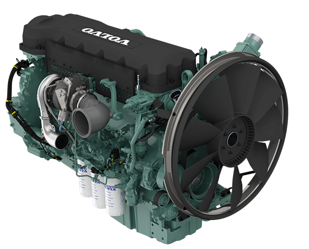
Engine
| Model | VOLVO |
| Model | TAD882GE |
| No. of cylinders & arrangement | 6 in linie |
| Cooling system | With water |
| Induction system | Direct injection with turbocharger |
| Displacement (l) | 7,7 (I) |
| Standby power (kWm) | 249 KWh |
| Speed (rpm) | 1500 rpm |
| Bore & Stroke (mm) | 110 x 135 mm |
| Compression factor | 17,2 : 1 |
| Regulator | Electronic |
| Total oil capacity (l) | 27 (I) |
| Engine coolant & radiator capacity | 46 (l) |
| Fuel consumption at 100% prime load | 58 (l / h) |
Standard features
Alternator Marelli
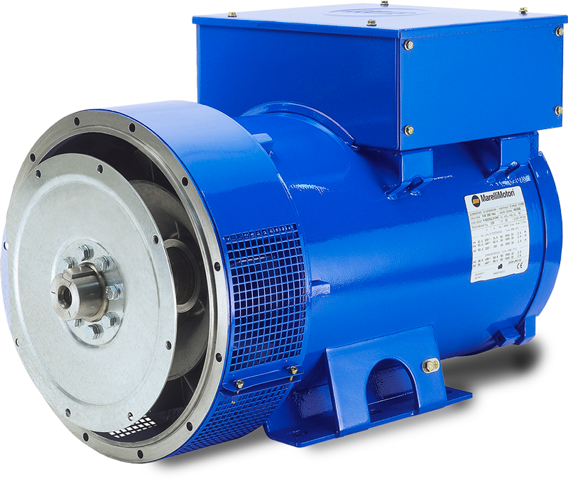
| Model | MXB-E 250 MB4 |
| Frequency (Hz) | 50 Hz |
| Concept | Brushless, 4 poles |
| Phases | 3 |
| Voltage (V) | 400 / 230 V |
| Protection class | H |
| Excitation system | Electronic |
| Performance | 93% |
| Protection | IP23 |
| Certification test | test EN 10204:2001 |
Control panel
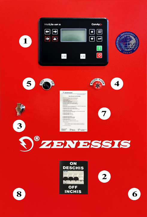
Made in metal box, IP54 degree, with lock. The control panel is equipped with ComAp Inteli Lite NT AMF25 control module, with the possibility to start and stop the generator set, both in automatic and electric mode. The control panel monitors the power grid and can command and control the ATS panel (automatic transfer switch).
Control panel standard specifications :
The command and control panel is mounted inside the casing, in a metal box with IP 54, equipped with a viewing glass, equipped with:
| Lite NT AMF25 control module |
| Static battery charger |
| Emergency stop button & circuit breaker fuses control |
| Overcurrent differential protection |
| Protection relays |
Control panel
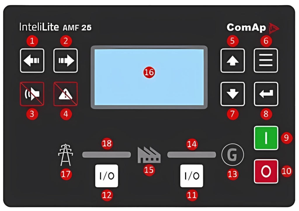
| 1. Left button |
| 2. Right button |
| 3. Horn Reset button |
| 4. Fault Reset button |
| 5. Up button |
| 6. Page button |
| 7. 7. Down button |
| 8. Enter button |
| 9. Start button |
| 10. Stop button |
| 11. GCB button. Works in MAN and TEST modes only 12. MCB button. Works in MAN and TEST modes only |
| 12. MCB button. 12. MCB button. Works in MAN and TEST modes only |
| 13. Generator status indicator |
| 14. GCB On. Green LEDs are on if GCB is closed and Gen-set is healthy |
| 15. Load |
| 16. Graphic B/W display, 132 x 64 pixeli |
| 17. Mains status indicator |
| 18. MCB On. The green LEDs are “on” when the MCB is closed and the network is within the preset parameters. |
Command module standard specifications:
| Microprocessor control |
| 132 x 64 pixeli LCD display |
| Programming on front panel as well as through PC software |
| Control buttons and soft touch navigation |
| Remote communication via USB or with optional modules via RS232, RS485, Ethernet or SMS |
| Store 180 events with date and time |
| Maintenance programming 3 levels |
| Engine heater control –Optional |
Configuration
Configuration
| 1. Lite NT AMF25 control module, |
| 2. Circuit Breaker protection |
| 3. Locks |
| 4. Alarm |
| 5. START button ON / OFF |
| 6. Hinges |
| 7. Maintenance schedule |
| 8. Metal box |
Displays:
| Engine – engine speed; oil pressure; coolant temperature; running time; battery voltage; maintenance data. |
| Alternator – voltage (L – L, L – N); current (L1 – L2 – L3); frequency; kW; Pf; kVAr; kWh,kVAh, kVarh; phase sequence. |
| Main network – voltage (L – L, L – N); frequency, mains ready; mains off; generator set ready, generator set disconnected, active power kW, apparent power kVA, reactive power kVA r, power factor, phase sequence. |
| Warning – battery faulty charging, low battery voltage, fail to stop, low fuel level, overload, phase reversing, speed sensor failure. |
| Alarms – low oil pressure, high engine temperature, under / over voltage, under / overfrequency, under / overvoltage, ECU fault -optional. |
| Status displays – missed start, emergency stop, low oil pressure, high engine temperature, under / overspeed, under / overfrequency, under / overvoltage, oil sensor, phase rotation, overload, overcurrent group, phase reversal. |
Static battery charger:
Made with TSD technology, with high efficiency. Protected for short- circuit currents, it can be used as a current source, input voltage 196-264 V, output voltage 27.6 V / 5A or 13.8 V / 5A.
Standards
Electrical safety / EMC, BS EN 60950; BS EN 60950 – 6 – 2 EMC; BS EN 61000 – 6 – 4 EMC.
Housing
Made of galvanized steel, painted in electrostatic field, soundproofed. It is modularly designed with in-door access doors on all sides of the generator. The exhaust pan is residential type, mounted inside the casing.
The housing are designed to optimize the cooling of the engine and alternator assembly, and can be mounted outdoors, providing protection against weathering and low noise levels. Painting is done with polyurethane paint with UV protection.
Housing
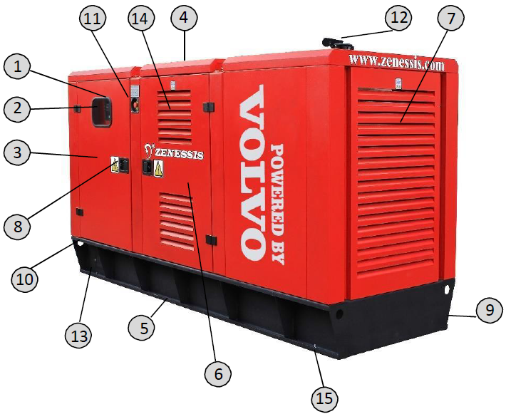
| 1. Command module |
| 2. View window |
| 3. Access door for control module |
| 4. Points for crane lifting (optional) |
| 5. Spaces for handling with the forklift |
| 6. Usa acces motor si alternato |
| 7. Air intake grills |
| 8. Handles provided with locks |
| 9. Fuel supply bus (optional) |
| 10. „Sleigh chassis” fitted with lifting/pulling holes |
| 11. Emergency button |
| 12. Exhaust Gas Valve |
| 13. Cable access space |
| 14. Hot air outlet grills |
| 15. Protective pads |
Dimensions and weight
Dimensions and weight of open genset
| Sizes (length x width x height) (mm) | 3200 x 1250 x 1750 |
| Weight (kg) | 2100 |
| Fuel tank capacity (liters) | 400 |
| Noise level (at 7m distance) | 85 db |
Dimensions and weight of the closed genset
| Sizes (length x width x height) (mm) | 3200 x 1250 x 1750 |
| Weight (kg) | 2519 |
| Fuel tank capacity (liters) | 400 |
| Noise level (at 7m distance) | 72 db |
Standard features
| Control & command panel with metal measuring & control devices, IP 54 protection rating |
| Static charger for. battery |
| Dynamic alternator charging batteries ori |
| Chassis with fuel tank sized for. 8 hours autonomy |
| Vibration dampers |
| Fuel level measuring device |
| Electrical lines protected with tubing & gland |
| Residential silencer |
| Thermostat heater ordered for. coolant |
| Oversized start battery |
| Emergency stop button |
| Protective pads |
| Metal hinges |
| Access doors with locks |
| Crane or forklift handling system |
| Flameproof and soundproof insulation |
Optional features
| Anti-condensation heating system. electrical panels |
| Fuel / oil heating system |
| Manual position switch AAR |
| Oil drain pump |
| Motorized AAR, patented invention ENDRESS-Brevet OSIM 00048/2015 |
| AAR transfer panel with 3/4 poles |
| 3/4 pole differential protection |
| 400 V/230 V socket |
| Coolant heating circulation pump |
| Fuel filter with water detection |
| Detour board – patented invention ENDRESS – Patent OSIM 00010/2012 |
| Trailer |
| Start by remote control |
| Groundless protection |
| Interior lightings with switches operated at doors opening |
| Liquid retention tray |
| Liquid leakage detection sensor |
| Remote monitoring & control system |
| External fuel feed nozzle with lock |
| Forklift pocket system integrated in the chassis |
| Fire extinguisher with internal housing support |
| Super soundproof housing |
| PowerLock force connectors with phase reversal interlock system |
| Intake air heating spark plug |
| Grounding electrodes |
| Fuel transfer automatic pump |
| Mobile distribution panel with 4 sockets |
| Cable reel |
| Fire detector with automatic shutdown generator set |
| Fire extinguishing system with inert gas |
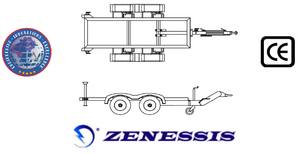
Optional: RAR approved auto trailer
Model: EGR 3500
Endress Group Romania S.R.L. certifications:
ISO 9001 : 2008, ISO 14001 : 2005, ISO 18001 : 2008.
ZENESSIS generator sets are CE compliant, and are tested according to EU noise legislation 2000/14/EC.
Reference ambient conditions: 1000 mbar; 25° C; 30% relative humidity; power according to ISO 3046 / ISO 8528 standards
Prime power (PRP) – ISO 8528
Primary power (PRP) – is the continuous power that a generator is capable of supplying continuously while supplying a variable electrical load when operating for an unlimited number of hours per year under agreed operating conditions, within the maintenance intervals and procedures prescribed by the manufacturer.
Standby power (ESP) – ISO 8528
Standby power (ESP) is the maximum power available at a variable load, under the operating conditions provided, that a generator is able to provide in case of power failure or under test conditions, maintenance intervals and procedures being performed as prescribed by the manufacturer.
